by John Ganter, ganter@etrademail.com, http://nerve-net.zocalo.com/jg/c/
A trigger strobe is a way of optically connecting a camera to flashguns. The camera fires the trigger strobe through a sync cord, then the light sets off slaves connected to the flashguns out in the cave. These flashguns can be either bulbs or strobes. The relatively small trigger strobe does not contribute light to the photo.
My first trigger strobe was a small K-Mart strobe encased in a piece of PVC pipe for mud and water resistance. A threaded sink trap coupling provided a water-resistant membrane for the power switch, and an opening for changing batteries. This worked well for several years, but eventually a wire broke inside. At this point I decided to try to build a new trigger strobe using an O-ring sealed enclosure. The advantages would be a better shape for packing (rectangular instead of tubular), more water resistance, and vibration resistance from tight packing and internal partitions. Due to tight space, I had to solder the AA batteries into the PVC model. In the new version, I hoped to have room for a battery holder. This would speed servicing in the field, where time is always limited.
My design priorities were these:
| 1) Small 2) Light 3) Rugged, water-resistant, safe for operator |
4) Reliable (minimize repair/rebuild) 5) Minimal construction time 6) Quick field maintenance |
I'll describe my project and show what worked and what did not. This is not an exact recipe for building a trigger strobe, but hopefully you will benefit from some of my discoveries and get ideas for similar devices. My project was carried out with home workshop tools and a couple of special-order commercial items. I used only hand tools, soldering equipment, and a drill. A parts list and sources are at the end.
Note that you will certainly void the warranty on the strobe you repackage, and you could ruin one or more in the construction process. Also, there are significant electrical hazards to the person doing the modification and to operators of the strobe. These will be discussed more below. This article is written to provide ideas to experienced and knowledgeable electronics hobbyists, and the author will not be liable for any consequences that occur.
Finding a strobe/enclosure balance
My main objectives were for the trigger strobe to be small and light. I usually carry a Nikonos III camera, two bulb guns and slaves, and flashbulbs. This adds up to a lot of volume and weight, which makes for a bigger pack and thus more drag resistance and work.
So I wanted the smallest available enclosure with a strobe that fit. It was difficult to strike this balance, because no strobe would fit in the smallest enclosure. The next larger enclosure was oversized for the strobe. I had to work back and forth between enclosures and strobes to try to find a good combination. Here are some details.
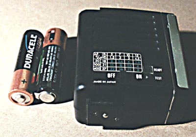 |
Hanimex X130 strobe with two AA batteries for scale |
The trigger strobe does not have to be very powerful if you use highly-sensitive slaves like the Firefly (1). So I obtained some small strobes (one or two AA batteries only). These included a Hanimex X130, a Phoenix 49S, a unit out of a Fuji (?) disposable camera, and a couple of Kodak Funsaver disposables.
According to Charlie Plantz, the disposable camera strobes are recycled multiple times and work fairly well as ultra-cheap cave strobes (you can usually get them free by asking nicely at a one-hour film lab). The first problem I saw with disposables is the circuit board shapes. They are designed to fit into the camera. Also, the Kodaks now have a timer to turn them off, which I did not want to deal with. While the single AA was appealing, I found that I could not fit these weirdly-shaped boards into the smallest enclosures I had.
The other problem with disposables is long-term reliability (design objective 4). I wanted this trigger strobe to last for many years with very low maintenance. Yes, I could get a disposable camera strobe for free, but if it only lasted for 1000 flashes then I would have to spend many hours pulling it out and replacing it.
Since I would have to use a larger enclosure anyway, I turned my attention to the Hanimex. This appeared to be a high-quality strobe that would last a long time.
Now for the enclosures. There are a variety of O-ring sealed enclosures (NEMA 4X) available from manufacturers like BUD, Hammond Rolec, Hoffman, and Rose. Materials are aluminum, polycarbonate, and other plastics. Closure is generally with four stainless steel screws that are outside the O-ring seal.
This market is very specialized. Enclosures generally have to be special-ordered, although some models are stocked by mail-order sources like Mouser. (February 2000: Newark has them on their website.) Since I could not go and handle the enclosures, I made cardstock models of them to try to figure out which ones to order.
 |
Cardstock
enclosure model. The BUD enclosure dimensions are drawn with Visio. The drawing is printed
on cardstock and cut out with scissors. It can then be folded and taped to give the approximate
outside dimensions of the enclosure. By stuffing components into the model, you
can get a sense of what will fit. This figure is not to scale or proportion. For drawing files of several brands and enclosures, contact the author. |
Many of the enclosures are large and/or have a blocky shape that is good for industrial controls, but not for handheld devices. BUD seems to have the best selection of smaller, more rectangular enclosures.
I ended up ordering several BUD enclosures through a local dealer: the PN-1320C, PN-1321C, PN-1322C, and PN-1330C. They cost $6 to $12 each. A major advantage is the the clear polycarbonate lid. This avoids having to build a sealed window for the strobe as I had to do on my K-Mart trigger strobe and the TU-83 project (2).
With enclosures in hand, it appeared that I would be able to fit the Hanimex into the PN-1321C. This enclosure has outside dimensions of 4.5 x 2.6 x 1.6 inches, and weighs 4 oz. The Hanimex would definitely fit into the PN-1322C, but this was 1/2-inch deeper and 1 oz heavier.
Sealed switches and cable gland
The third and fifth design objectives were ruggedness/water resistance/safety and minimal construction time. In previous projects, I have built rubber membranes that allow switches to be operated from outside the enclosure. The advantage of this approach is that the switches are recessed, which makes them extremely resistant to accidental operation and which streamlines the outside of the housing. The disadvantages are more space required inside, and increased construction time. Membrane switches are a pain to build because of the number of enclosure penetrations, building a mounting bracket for the switches, etc.
I decided to try rubber switch boots. The time savings was very appealing. Also, if they wear out they can be quickly replaced with a pair of pliers. Like O-ring enclosures, rubber switch boots are not easily found but I ordered an assortment from Newark in order to find the right size and thread. They are $3 to $4 each.
I needed one on/off push switch for power, and one momentary contact push switch for manual trigger. I used an Alco miniature DPDT switch for power. This was available surplus for $2. The second pole is used for a separate circuit that operates an LED to show when the power switch is on.
The momentary pushbutton is a E-Switch, which cost $6 from Mouser. Both of the switches are very high quality, in keeping with objective 4. I don't want to have to replace them.
I discovered that the N5030 boot fits both of these switches. (The Alco shaft must be cut down and filed smooth. But see Results below.)
For the synch cord, I obtained a BUD PG-7 cable gland. This is a nicely-made strain relief that grips the cable tightly and with high water resistance. It costs about $2 and will accept 0.118 to 0.256 inch diameter cable.
Disassembly of the strobe
The strobe manufacture forbids disassembly because this exposes hazards. It is important to understand these hazards before proceeding:
| HAZARDS IN DISASSEMBLY If shorted, the main strobe capacitor will produce an arc and/or serious shock. It should be be handled with caution. Before opening the case, the power should be switched off and the flash discharged completely. Immediately upon opening the strobe the main capacitor should be discharged through a 10 ohm, 10 watt power resistor for about 30 seconds. HAZARDS IN USE In wet environments, any strobe presents a serious shock hazard to the user. There is also some hazard from exploding hydrogen gas that may evolve from the batteries. Since the user is likely to be a photo assistant who has no knowledge of the strobe's hazards, it is the responsibility of the strobe builder and owner to
This protection is primarily through design, construction, maintenance, and testing of the strobe enclosure. These tasks are the responsibility of the strobe builder and owner. |
I carefully disassembled the Hanimex so that I could try it in the BUD enclosure. From previous experience I knew there would be a lot of handling, so I was careful to minimize stress on the board and wires.
Assembly
The first thing I did was to install the switches and cable gland. I had to carefully visualize the spacing of the three items and make measurements to get them all to fit.
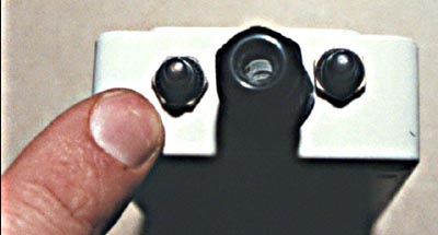 |
Cable gland and the two switch boots installed in the end of the BUD 1321 enclosure. |
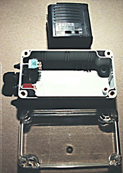 |
With the switches and boots installed, you can see how the enclosure and lid compares in size to the Hanimex strobe at the top. |
It was looking like everything would fit. At this point the Hanimex stopped firing. I had apparently broken something in testing the fit. I could not figure out what the problem was, so I gave up and used the Phoenix 49S which also seemed to fit. This was a more expensive item, but I had gotten it used and realized that I could waste a lot of time trying to fix the Hanimex.
The first thing that I did was to pot the Phoenix in hot glue. This helps to prevent damage to the board and wire connections during fitting and assembly. Once the strobe is in use, it protects against shock and vibration. Hot glue is not good where heat or humidity is present, but I felt it would work in this application. Silicone would be better. I left space for heat dissipation around the thyristor.
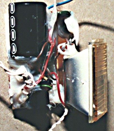 |
The Phoenix 49S strobe components have been potted with hot glue to protect them from bending during assembly and shock during transport and use |
Now that I knew how much volume the switches and the strobe itself were going to consume, I started to partition the housing (photo below). I was prepared to use two AAA batteries if space was really tight. These would be smaller and lighter than AAs (Objectives 1 and 2), but would also need to be replaced more frequently in the field (contrary to Objective 6). There seemed to be enough space, so I went with the AAs.
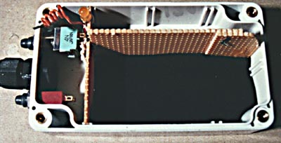 |
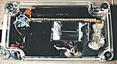
Housing with partitions installed. The
partitions are made from electronic perf board, wired together and wedged into the card
slots in the housing. The battery area is at the top. The yellow LED to indicate "power on" is visible at the top left. A bed of 3/8-inch wetsuit neoprene has been placed for the strobe parts in the bottom right area. |
The Sync cord
For flash connections I use 120VAC household connectors (see discussion in 2). I made the trigger strobe connector from a 'grounding adapter,' one of those things that you use at home to convert 3 bladed plugs to 2 bladed receptacles. I slipped on a length of vinyl tubing, then soldered the cable to the adapter blades and installed several cable ties. I then wrapped the assembly in masking tape and filled it with AquaSeal (3). The result is a very durable connector assembly. Note that the connection does need to be wrapped with several turns of electrical tape in wet conditions.
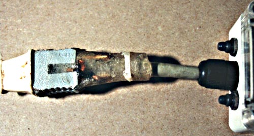 |
Synch connector made from 120VAC components. From left to right: extension cord plug from camera inserted into grounding adapter, grounding adapter soldered and then potted into vinyl tubing and cable with AquaSeal. |
Final assembly
Finally, I stuffed everything inside. It fit! Just barely. I added strips of neoprene as extra padding, particularly on top of the relatively heavy and loose battery holder.
 |
The completed trigger strobe with the lid closed. The strobe tube is at center, the battery holder at the top. The "ready light" has been glued to an aluminum foil reflector and is at the lower right. |
Since the trigger strobe is sealed, I included a hydrogen catalyst and moisture absorber. This is a small bag made from stocking material and filled with a mixture of platinum catalyst pellets and silica gel. This is an important safety feature; see discussion in the TU-83 article (2).
Results
The first thing I did was place the unit in a foot of water and look for bubbles. It did not leak! A foot is quite sufficient for the caving I do, and I did not try it any deeper. I will continue to test the unit periodically.
The second thing I did was add a lanyard by running it through one of the mounting holes (outside the O-ring). I carefully sized the lanyard so that with a micro-carabiner it will clip on my battery belt, seat harness, or the Nikonos strap just right.
I have used the trigger strobe for about 40 hours of damp and muddy caving and it has performed well. The boot on the Alco switch has developed a small tear. Apparently it does not fit properly after all. Fortunately, the Alco switch includes an internal O-ring seal, so I am not in a hurry to replace the boot or switch. The switch would be difficult to change out, and there does not seem to be a boot in the Hexseal line that truly fits it.
Conclusions
Assembly took about 12 hours once I had all the parts in hand. This is a lot of time, but there were many small problems and decisions that had to be made. I achieved the design objectives in a reasonable fashion. The trigger strobe weighs 9 oz and is about twice the size of the original strobe. I have made a neoprene case for it, and I expect (hope) to throw it in my cave pack with no other protection for many years to come.
It should be possible to make a truly tiny trigger strobe using the BUD 1320C or 1330C enclosure, but circuit board shape is a real problem. All of the really tiny boards that I have seen are oddly-shaped in order to fit inside compact cameras.
Parts List
| Part | Manufacturer | Source |
| BUD enclosure PN-1321C |
BUD Industries, http://www.budind.com/ | Newark, http://www.newark.com/ $12 |
| Cable gland, PG-7 NG-9511, 0.118 to 0.256 inch |
BUD Industries | Newark, http://www.newark.com/ $2 |
| (2) Switch boots, 1/4-40 N5030 |
APM HexSeal, http://www.apmhexseal.com |
Newark, http://www.newark.com/ 30F011, $4 each |
| Miniature push on/push off MPB206N * |
Augat/Alcoswitch | All Electronics, http://www.allelectronics.com/ MPB-20, $2 |
| Pushbutton momentary switch SP7B10M1RE |
E-Switch, http://www.E-Switch.com/ |
Mouser, http://www.mouser.com/
612-700-B112, $6 |
| small AA-powered strobe | various | used |
| Double AA battery holder | various | Mouser |
| Perf board | various | All Electronics |
| AquaSeal | McNett | Outdoor Wilderness Fabrics, http://www.owfinc.com |
| Neoprene | various | Outdoor Wilderness Fabrics |
*This is a very nice switch but even cut down it is too big for the N5030 boot.
Notes
(1) The Firefly is a commercial version of the David Gibson cave slave design (http://www.sat.dundee.ac.uk/~arb/creg/slave.html). It is imported to the US by Peter Jones, pjcaver@mint.net
(2) The TU-83: A Ruggedized Caving Strobe. http://nerve-net.zocalo.com/jg/c/tech/tu83/
(3) AquaSeal http://nerve-net.zocalo.com/jg/c/tech/aquaseal
(4) Nikonos sync cord connections. http://nerve-net.zocalo.com/jg/c/tech/nikonos/
Bibliography
Don's Xenon Flash and Strobe Page. http://www.netaxs.com/~klipstei/donflash.html
Version 2, 15 February 2000
![]()
![]() Caving Technology
Website home
Caving Technology
Website home ![]() Copyright and Disclaimer
Copyright and Disclaimer ![]() Feedback
Feedback